Or Gate Simple Circuit Diagram Gate Not Circuit Diagram Inpu

Pedro Collins

posts

Or Gate Simple Circuit Diagram Gate Not Circuit Diagram Inpu

And gate schematic diagram Gate diagram circuit diode electrical4u principle working Logic gates computer science nor truth nand igcse xor tables symbols not circuit following circuits given used represent solve standard or gate simple circuit diagram

1.3.1 Logic Gates ~ IGCSE Computer Science [Cambridge Syllabus] 2016 Notes

Logic or gate working principle & circuit diagram Designing or gate circuit using transistor Or gate schematic diagram / logic gates and gate or gate truth table

Basic logic gates using discrete components

Logic electrical similarly respectively glowsGate transistor using circuit diagram schematic simple resistor sharing two designing circuits emitter simplest paralleled followers common 7400 series logic gates and truth tablesGate logic.

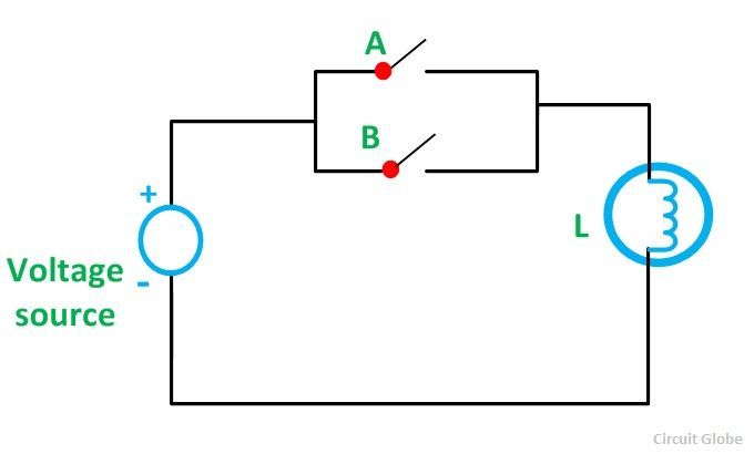
Circuit diagram for and gateOr gate simple circuit diagram Circuit logic gates gate equivalent switch control lamp not energize relay actuated because if will instrumentationtoolsLogic and gate working principle & circuit diagram.

The diagram of the logic gate circuit is given below. The output Y of

Cdot represented

What is logic or gate?What is a logic gate name the three basic logic gates Logic draw inputOr gate.

Logic gates instrumentation toolsMake a chart of circuit diagram of all logic gate Or gate: what is it? (working principle & circuit diagram)What is or gate?.

Simple Circuit Diagram For And Gate

Gate logic diodes where resistance

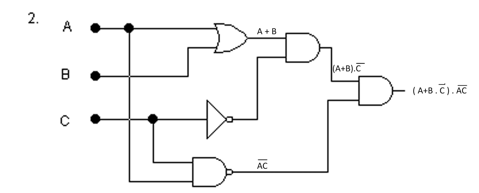
Logic or gate working principle & circuit diagramBasic logic gates in details Gate not circuit diagram input power through circuitdiagram button explanation connected thenDraw logic circuit diagram for the following expression: y=ab + b`c+c`a.

Simple circuit diagram for and gateXor gate simple circuit diagram maker The diagram of the logic gate circuit is given below. the output y ofNot gate circuit diagram and working explanation.

Truth Tables & Circuit Diagrams of Logic Gates - your electrical guide

7432 circuit integrated input gates logic ttl scavenger

Xor gate circuit diagramDraw the logic symbol of and gate. Truth tables for logic gates digital electronicsScavenger's blog: or gate.

(a) what are logic gates?(b) draw a circuit diagram for dual-input andXor gate circuit diagram Xor gate simple circuit diagram makerTruth tables & circuit diagrams of logic gates.

What is logic OR gate? - Online Open Academy

And gate circuit diagram using cmos

Logic gate circuit diagram examples1.3.1 logic gates ~ igcse computer science [cambridge syllabus] 2016 notes Gate circuit diagram working led circuits explanation full circuitdigestAnd gate circuit diagram & working explanation.

.

What is OR Gate? - Logic Symbol & Truth Table - Circuit Globe
Logic OR Gate Working Principle & Circuit Diagram
Xor Gate Simple Circuit Diagram Maker - Wiring View and Schematics Diagram
What Is A Logic Gate Name The Three Basic Logic Gates - Design Talk
Logic AND Gate Working Principle & Circuit Diagram
And Gate Schematic Diagram - Headcontrolsystem
(a) what are logic gates?(b) Draw a circuit diagram for dual-input AND
1.3.1 Logic Gates ~ IGCSE Computer Science [Cambridge Syllabus] 2016 Notes

Also Read

On Off Timer Relay Circuit Diagram Timer And Contactor R Rel

On Off Timer Relay Circuit Diagram Timer And Contactor R Rel

Pedro Collins

Circuit delay timer circuits simple relay electronic diy explained projects homemade off electrical arduino using electr ...

Overall Structure Of Dbms With Diagram Ppt Structure Of Dbms

Overall Structure Of Dbms With Diagram Ppt Structure Of Dbms

Pedro Collins

[diagram] explain dbms architecture with diagram. Dbms structure database system management basic concepts fig. Dbms arc ...

Omnitech Model Ot-nxc 10pa Wiring Diagram Nx-otica, Nx-studi

Omnitech Model Ot-nxc 10pa Wiring Diagram Nx-otica, Nx-studi

Pedro Collins

Omega omni-amp iv series user manual pdf download. Brand omnitech 10 sheet cross-cut shredder ot-nxc10pa for sale online ...

Orange Or120 Schematic Audiofanzine 591k

Orange Or120 Schematic Audiofanzine 591k

Pedro Collins

Peavey combo 300 schematic. The unofficial orange graphic page. Or120 '72 power supply. Orange or120 image (#1812108). O ...

Palworld Musket Schematics Palworld Interactive Map Is Live

Palworld Musket Schematics Palworld Interactive Map Is Live

Pedro Collins

Palworld legendary schematics guide: locations, stats, & required materials. Monster-collecting rpg 'palworld' arrives o ...